Cart

Your Shopping Cart is empty.

Continue Shopping

Psk-31 "EASY DIGI™" Sound Card Interface PSK RTTY FT-8 FT-4 JT-65 PCB KIT

$7.00  $4.19

Up To 50% Off,30-Day Returns
Add to Wish
  • All returns accepted: Returns Accepted
  • Band: ALL
  • Brand: EASY DIGI™
  • Compatible Model: Almost all HF, VHF, and UHF amateur radios
  • Condition: New
  • Country/Region of Manufacture: United States
  • Item must be returned within: 30 Days
  • MPN: Easy Digi PCB Kit
  • Manufacturer Warranty: None
  • Refund will be given as: Money Back
  • Restocking Fee: No
  • Return shipping will be paid by: Buyer
  • To Fit: Ham Radio Receiver
  • Type: Interface board kit
  • Year Manufactured: 2020
  • 1000 Units in Stock
  • Location:Los Fresnos, Texas
  • Ships to:Worldwide
  • Condition:New
  • heart Popularity - 72439 views, 10348.4 views per day, 7 days on eBay. Super high amount of views. 1103 sold.
  • usd Price - Avg: $0.00, Low: $0.00, High: $0.00. Best quality when compared to PicClick similar items.
  • star Seller - + items sold. 0% negative feedback. Great seller with very good positive feedback and over 50 ratings.
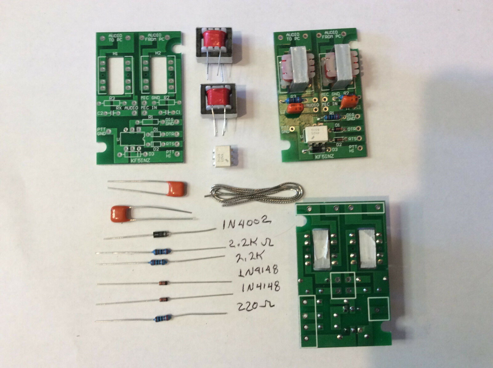
No, we didn’t re-invent the wheel, we just made a convenient, single board, isolated, digital interface that works for almost all of the digital modes on HF and VHF/UHF. Works with DIGIPAN, FLDIGI, MTTY, MMSSTV, JT-65, FT-8, and most all other sound card programs! Work PSK-31, PSK-63, RTTY, SSTV, NBEMS, plus many other modes on your HF or VHF/UHF rig.<br>Nothing new about this technology, it consists of two 600 ohm line transformers for audio input and output from your pc to your transceiver, and an opto-coupled push to talk circuit that works off of an RS-232 port on your computer.<br>·<br>Transformer coupled audio eliminates ground loops and AC hum on your signal<br>·<br>Opto Coupled push to talk circuit also eliminates ground loops and false triggering of your PTT lines.<br>·<br>Very small size, only 2 1/16” x 1 3/8” x .625” high, can be incorporated inside of many radios, with only your RS-232 cable coming outside of the radio.<br>·<br>Weighs less than 3 ounces<br>·<br>High quality FR-4, solder masked, silk screened Printed Circuit Board<br>·<br>Compatible with most modern ham radio transceivers.<br>These interfaces have been tested on many Kenwood , Icom, Yeasu, and other brand radios.<br>Simply assemble and hook up per the enclosed wiring diagram and load your software, configure your com port, turn on the radio and have fun on your favorite digital mode!<br>ITEMS INCLUDED IN YOUR KIT. PLEASE INVENTORY YOUR KIT.<br>1N4001 DIODE<br>1 ea<br>1N4148A DIODE<br>2 ea<br>2.2K 1/4W RESISTOR<br>2 ea<br>430 OHM 1/4W RESISTOR<br>1 ea<br>4N25 OPTO COUPLER<br>1 ea<br>.1UFD CAPACITOR<br>2 ea<br>600:600 AUDIO TRANSFORMERS<br>2 ea<br>PCB<br>1 ea<br>Solder<br>12”<br>It is assumed that you have a 25 – 45 watt soldering iron. Pencil type tips are preferred. Use of a soldering GUN is NOT recommended due to the small sizes of the solder pads and small spacing between pads. You will also need a pair of wire cutters and a pair of needle nose pliers. The 12” of solder supplied should be enough to solder several of these boards – use the solder sparingly – to end up with a professional looking and operating board with no solder shorts. This board should take approximately 15 minutes to assemble and solder.<br>1.)<br>Using the printed circuit board layout, find the locations for the two 1N4148A Diodes and install them.<br>Observe the polarity. The band on the diode must be oriented to the band on the circuit board layout.<br>Bend the leads so that the diodes lay flat on the circuit board.<br>Solder and clip the leads off close to the board.<br>2.)<br>Find the locations for the two 2.2k 1/4W Resistors and install them.<br>Bend the leads so that the resistors lay flat on the circuit board.<br>Solder and clip the leads off close to the board.<br>3.)<br>Find the location for the 430 ohm 1/4W Resistor and install it.<br>Bend the leads so that the resistor lays flat on the circuit board.<br>Solder and clip the leads off close to the board.<br>4.)<br>Find the location<br>for the 1N4001 Diode and install it.<br>Observe the polarity.<br>The band on the diode must be oriented to the band on the circuit board layout.<br>Bend the leads so that the diode lays flat on the circuit board.<br>Solder and clip the leads off close to the board.<br>5.)<br>Find the location for the 4N25 optocoupler IC, and install it.<br>Pin1 of the opto-coupler is indicated by a small circular indentation in the top left corner of the IC.<br>Orient pin 1 of the opto-coupler to the<br>pin1 location on the circuit board.<br>The leads of the opto-coupler will need to be bent inward a slight amount to fit into the circuit board.<br>After installing the 4N25 optocoupler IC, solder the 6 leads.<br>6.)<br>Find the location for the two .1ufd capacitors and install them.<br>The capacitors are NOT polarized, so they can be installed either direction.<br>Push the capacitors down close to the board but do not force them completely down or you will break the body of the capacitor.<br>Solder and clip the leads off close to the board.<br>7.)&